-
Project – Rotary-Linear Hybrid Axes for Meso-scale Machining
PI(S):
Read more: Project – Rotary-Linear Hybrid Axes for Meso-scale MachiningSponsor(s):
-
Project – Actuator Calibration Fixture
PI(S):
Read more: Project – Actuator Calibration FixtureSponsor(s):
-
Project – Six Degree-of-Freedom Oil Floated Magnetic Suspension
PI(S):
Sponsor(s):
Read more: Project – Six Degree-of-Freedom Oil Floated Magnetic SuspensionThe device uses active magnetic bearings in combination with squeeze film dampers to form a very stable, vibration resistant motion control stage. Total travel is within a cube of 100 microns, and resolution in the linear axes is better than 0.5 nm. One possible application involves providing the sample motions required in scanned probe microscopy.
The Angstrom Stage is a six degree of freedom positioning stage for fine motion control. The stage ac
hieves a 6-sigmapositioning noise of 0.3 nm at 1 Hz measuring bandwidth and a controller bandwidth of 5 Hz. Total travel is within a cube of 100 microns. The single moving element is immersed in oil, forming squeeze film dampers between itself and the frame. This design results in a highly overdamped and vibration resistant system. Twel
ve electromagnets provide the forces necessary to suspend and servo the platen while six capacitance probes sense the position. All of the control algorithms are performed digitally, using a PC-based digital signal processing
board. The controller performs two functions that are essential to achieving 0.1 nanometer positioning resolution. First, it uses a detailed model of the stage in a feedback linearization scheme that linearizes and decouples the degrees of freedom. Second, it uses a combination of a digital filter and an estimator to reduce the effect of measurement noise by about two orders of magnitude. The end result is a stage that is suitable for positioning a sample with better than atomic resolution. Envisioned applications of the stage include producing the scanning motions required in scanned probe microscopy or as a motion control stage for integrated circuit metrology.
-
Project – Electromagnetic Actuator for a Scanning Mirror
PI(S):
Read more: Project – Electromagnetic Actuator for a Scanning MirrorSponsor(s):
-
Project – Thermally Efficient Linear Motor
PI(S):
Read more: Project – Thermally Efficient Linear MotorSponsor(s):
-
Project – Magnetically Suspended Artificial Heart Pump Impeller
PI(S):
Sponsor(s):
Read more: Project – Magnetically Suspended Artificial Heart Pump ImpellerThis is a public disclosure of key ideas developed in our laboratory for magnetically suspending a heart pump impeller. This research was supported by the Charles E. Reed Faculty Initiatives Fund.
Introduction
Our Precision Motion Control Lab designs, builds, and controls electromagnetic systems. We have developed magnetically levitated stages for photolithography, an Angstrom positioning stage for scanned probe microscopy, and high force density linear motors. Recently, we envisioned a six-degree of freedom magnetic suspension capable of large rotations about one axis. Such a system is similar to one of our photolithography stages which is a six-degree of freedom magnetic suspension capable of large translations in two dimensions. However, the application for our rotating system is to magnetically suspend and rotate the impeller in a centrifugal artificial heart pump. This has recently been done with many magnetic actuators and a separate motor to spin the impeller.
Our idea is to use principles from our prior work—namely that the motor can act as the bearings and suspend the impeller without the need for many additional actuators—to accomplish this task more effectively.
Prior Magnetic Suspension
Our flying puck, magnetically levitated photolithography stage is an example of a six degree of freedom stage that integrates drive force and bearings into the same actuators. Won-jong Kim built this stage which is the first to provide all the focusing and alignment motions required for photolithography with one moving part. This is possible because the four linear motors provide suspension as well as driving forces for the 5.6 kg platen supported against gravity. This stage has a 50 mm travel in the x and y directions, 400 µm in the z direction, and can perform milliradian-scale rotations about each of its three axes. Three laser interferometers and three capacitance gauges are used for feedback. The stage has a position noise of 5 nm rms in the x and y directions and can accelerate at 10 m/s2.
Rotating Suspension Idea
A variant on this stage is one in which the suspended platen would be able to spin completely around its vertical (z) axis, and the other five degrees of freedom would be capable of fine adjustments. This could be accomplished by arranging the linear motors in a circular pattern. The suspension force for the moving part is provided by the linear motors just as in the photolithography stage. This spinning six degree of freedom stage could have many applications such as in vacuum pumps, machine spindles, and robotics. The application we are most excited about is as the impeller in a centrifugal artificial heart pump. Magnetic suspensions have recently been used in this regard due to the stringent requirements on such a device. Our proposed suspension and drive technique is superior to those currently used since it reduces the number of actuators required to magnetically suspend and spin the impeller.
Conventional Heart Pumps
Each year approximately 50,000 people need heart transplants, but only 2,000 hearts are available. Artificial hearts and left-ventricular-assist devices can sustain life until a donor heart can be found. Eventually, it is hoped that artificial hearts might be good enough to be a permanent solution themselves. The engineering problem of creating an artificial heart is complex. Since the 1950's researchers have designed many mechanical heart pumps. Reliability problems with mechanical parts, valves, and clotting of blood have hampered these efforts. Many of these machines were also large and cumbersome whereas we would like to have a totally implantable design. In the last fifteen years the biomedical community has focused mostly on rotating pump designs since they are compact and avoid stagnation and clot formation in the blood. Mechanical ball bearings for the rotating pump have led to clotting and cell death, and studies show that these devices have lifetimes of only months. Lately, magnetic bearings have been used to completely suspend the pump's rotor in the heart pump. This solution allows large clearance passages for the blood flow and eliminates mechanical contact and wear.
Others have designed magnetic suspensions that use a brushless motor to spin the impeller and many electromagnets to regulate the other five degrees of freedom. Although all three axes and three rotations are controlled magnetically, the motoring mechanism rotating the impeller is totally separate from the bearing mechanisms used to control the three translations, and two other rotations.
Integrated Drive & Bearings
Our design unifies the bearings and the motor. Our motor spins the impeller and also can regulate the other five degrees of freedom. This results in a simpler, more compact design. Since each segment of the motor can provide drive and suspension forces, it is easier to design for redundancy and robustness which are essential in this application.
Figure 1 shows a possible layout for our integrated motors. We show six motors, but only three are required to generate all required motions. The impeller has a single circular magnet array on one side which faces a set of stators in the heart pump housing. Each stator can generate vertical suspension force and horizontal drive forces as shown in Figure 2. Differential operation of the motors allows control of all six degrees of freedom.
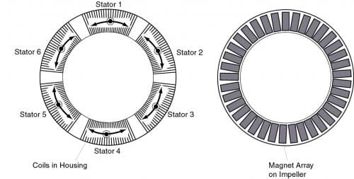
Figure 1: We show the actuators which suspend and spin the impeller. The impeller has a single circular magnet array on one side which faces a set of stators in the heart pump housing. Only three stators are needed to control all six degrees of freedom including full rotations about an axis out of the paper. We show six stators in this design so three of them are redundant.
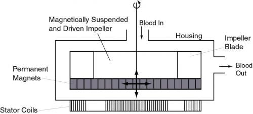
Figure 2: A cross sectional view of the impeller is shown. Each stator can generate vertical suspension and horizontal drive forces. Differential operation of the motors allows control of all six degrees of freedom.
Figure 3 shows examples of how the same actuators can drive the impeller and act as bearings. In Figure 3 (A), we see that we can generate torque to spin the impeller for its normal operation. This configuration of forces is equivalent to the rotary motor in conventional designs which separate the motor and bearings into different actuators. In Figure 3 (B), we show a fine translation adjustment using just two of our actuators. These are the same actuators that spin the impeller, but now they are acting as bearings. The other four degrees of freedom can be generated in a similar fashion; three of them require the use of the vertical forces shown in Figure 2.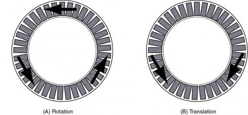
Figure 3: We show two examples of how the forces generated by the actuators can be combined to produce rotations and translations. We use only three actuators in these examples. In (A) we show the forces producing the normal rotation of the impeller. In (B) we show a fine translation adjustment.
The advantages of our design are:
Improved magnetic actuator and suspension design over existing designs comprising a multitude of actuators. The actuators can provide both suspension and drive forces to simplify the magnetic suspension.
Compact and integrated control, sensing, and power electronics so that the system will be implantable.
Redundant and robust actuators and sensors so that the pump will continue to work at some level in case of partial actuator or sensor failure.
Neutrally buoyant impeller to resist disturbance forces which will be encountered as the heart pump is accelerated when its host person moves around.
Low power consumption so that recharging is required less frequently.
Self-sensing motor operation by using the back EMF to get position and allow for sensorless commutation.
-
Project – Integrated Capacitance Sensors
PI(S):
Read more: Project – Integrated Capacitance SensorsSponsor(s):
-
Project – High-Precision Planar Magnetic Levitation
PI(S):
Sponsor(s):
Read more: Project – High-Precision Planar Magnetic LevitationThese pictures show our linear-motor-levitated stage for positioning wafers for photolithography. This stage was developed by Dr. Won-jong Kim in his Doctoral thesis under the supervision of Prof. David L. Trumper of the MIT Department of Mechanical Engineering. The stage uses the novel levitation linear motors developed in Dr. Kim's thesis to both suspend and position a 5 kg platen in three translational (x,y,z) and three rotational (theta-x, theta-y, theta-z) degrees of freedom, with nanometer resolution. Such stages will be of increasing utility in advanced semiconductor production systems such as wafer steppers which require nanonmeter-resolution positioning in six degrees of freedom.
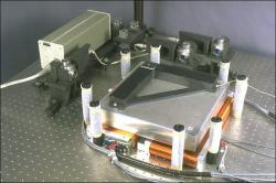 The first picture shows the stage sitting on its four linear motors. In the background is the laser interferometer which is used for position measurement for motions in the X-Y plane. This system has nanometer-level resolution. Motions out of the plane (Z) are measured with three capacitance gages which are located under the stage.
 The stage is made of aluminum skins on an aluminum honeycomb core. A set of four magnet arrays are attached to the bottom of the stage. The triangular object on top of the stage is a mirror which reflects the laser beams to form the moving target in the interferomter.
When active, the stage is levitated 300 micrometers above the rest position via the four linear motors. Each linear motor is capable of providing a levitation force in the vertial direction, and a translational force in the X or Y directions. Two of the motors are oriented in the X-direction and two motors are oriented in the Y-direction. By coordinating the four motors, each with two independent forces, the six stage degrees of freedom can be controlled in a redundant fashion. The control calculations are carried out on a digital signal processing system at a 4 kHz update rate.
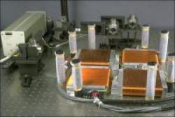 The second photo shows the four motor coil sets with the stage removed. In this photo you can see that the coils of two of the motors are oriented in X (right-left) and the coils of two of the motors are oriented in Y (front-back).
-
Project – Control Techniques for a Single Degree-of-Freedom Magnetic Suspension
PI(S):
Sponsor(s):
Read more: Project – Control Techniques for a Single Degree-of-Freedom Magnetic SuspensionThis project involves the design and implementation of various linear and nonlinear control schemes for a single DOF magnetic suspension. Plant uncertainty is introduced on purpose and countered using Robust and Adaptive techniques. Robust adaptive control is found to give the best results.
Control techniques for a single DOF magnetic suspension
Research in the precision motion control lab is targetted towards obtaining very rapid and precise positioning such as those required in stepper stages for Photolithography during semiconductor manufacture. A six dof stage has been built by Mark Williams for this very purpose. We use magnetic bearings to levitate the stage and allow for fine positioning and linear motors to provide the long axes of travel. The current approach to controlling the stage position is using feedback linearization. The six dof stage is a multi-variable control problem with coupling in between the various axes of motion. So, a simple single dof stage was built where a mass is levitated in between two E-core actuators which are standard in our lab.
My goal is to obtain faster responses and very rapid settling times. I am also studying the effects of parameters uncertainty. Control techniques that I have implemented on the single DOF stage include sliding mode control, robust adaptive control. Both techniques lead to higher bandwidths than those currently obtained. I am currently studying stiffness properties of the various control techniques.
-
Project – Magnetically Levitated Wafer Stepper for Photolithography
PI(S):
Sponsor(s):
Read more: Project – Magnetically Levitated Wafer Stepper for PhotolithographyWafer steppers are used in photolithography to position the uncut silicon wafer underneath a lens assembly in order to expose each of the future microchips. As such, the machine is required to have long travel, sub-micron resolution, and a settling time that is as fast as possible. The faster the machine settles, the more microchips can be produced. Typically, steppers are approached by stacking a short-travel, high resolution stage on top of a long-travel, low resolution design. This can lead to difficulties in achieving fast settling times. Our design uses magnetic bearings in combination with a six phase linear motor to combine the actions of the coarse and fine stages into a single moving element, thus allowing the long travel, high resolution, and fast settling times required.
Six Degree of Freedom MagLev Photolithography Stage
 Magnetic bearings are capable of applying force and torque to a suspended object without rigidly constraining any degrees of freedom. Additionally, the resolution of magnetic bearings is limited only by sensors and control, and not by the finish of a bearing surface. For these reasons, magnetic bearings appear to be ideal for precision wafer positioning in lithography systems. To demonstrate this capability a linear magnetic bearing has been constructed which uses variable reluctance actuators to control the motion of a 14.5 kg suspended platen in five degrees of freedom. A Lorentz type linear motor of our own design and construction is used to provide motion and position control in the sixth degree of freedom. The stage performance results verify that the positioning requirements of photolithography can be met with a system of this type.
-
Project – Noncontact Processing of Fibers, Beams, Webs and Plates
PI(S):
Sponsor(s):
Read more: Project – Noncontact Processing of Fibers, Beams, Webs and PlatesIn some industrial operations, it may be advantageous to handle the material without directly touching it, such as plastic film production, coating, and painting. This project explores the magnetic and electrostatic suspensions of flexible structures such as fibers, beams, webs, and plates. The research involves design of noncontact sensors and actuators, and study of suspension and vibration control.
Motivation
This project arose from a consultation involving a metal broom handle manufacturing plant. The handle makers calculated that they could save a significant amount of money if they made the process continuous. Beginning with a flat piece of steel which is rolled and seam welded into a tube, the soon-to-be broom handle is moved through the painting, heating and curing stations at about 1 meter per second. While this happens, the tube cannot be touched by rollers without marring the surface finish, so it is magnetically levitated with ten magnetic suspension stations for the 35 meters it takes for the paint to be applied and to harden.

Abstract
Our current project is a slight tangent from the original, with a more broad focus not only on beams but fibers, plates and webs as well. The problem is now three-fold: design and construction of a new position sensor; design and construction of a new actuator, and implementation of a control scheme for the system. To test the system we built an eight station, 1/10 scale model using the designed sensors and actuators to control the position of the tube.
Click here for more information on the following topics:
Actuator design
Sensor design
Suspension experiments of 2ft beam
Suspension experiments of 10ft beam
Controller design
Sensor/actuator positioning: averaging method
Publications
D. L. Trumper, M. C. Weng, and R. J. Ritter, "Noncontact Processing of Fibers, Beams, Webs, and Plates," NSF Grantee's Conference, January 1999.
D. L. Trumper, M. C. Weng, and R. J. Ritter, "Magnetic Suspension and Vibration Control of Beams for Non-contact Processing," Proceedings of the 1999 IEEE Conference on Control Applications, pp.551-557, August 22-27, 1999.
M. C. Weng and D. L. Trumper, "A Design Method for Magnetic Suspension and Vibration Control of Levitated Beams for Noncontact Processing," Proceedings of the 5th International Symposium on Magnetic Suspension Technology, December 1-3, 1999.
M. C. Weng, X. Lu and D. L. Trumper, "Magnetic Suspension of Flexible Structures for Non-Contact Processing," 7th International Symposium on Magnetic Bearings, Zürich, Switzerland, Aug., 2000.
M. C. Weng, X. Lu and D. L. Trumper, "Vibration Control of Flexible Structures Using Sensor Averaging and Acutator Averaging Methods," IEEE Transaction on Control System Technology, to be accepted.
X. Lu, M. C. Weng and D. L. Trumper, "Robust Moment Control of Flexible Structures Using Sensor Averaging and Acutator Averaging," IEEE Transaction on Control System Technology, to be accepted.
-
Project – Atomic Force Microscope Probe with Metrology, for Subatomic Measuring Machine (SAMM)
PI(S):
Sponsor(s):
Read more: Project – Atomic Force Microscope Probe with Metrology, for Subatomic Measuring Machine (SAMM)Together with UNC Charlotte, we have built a magnetically-suspended stage designed to achieve 0.1-nm resolution, 1-nm repeatability, and 10-nm accuracy over a macroscopic range of 25 mm in X,Y and 100 microns in Z. To complete the project, we are currently developing an atomic force microscope head to allow accurate characterization of the performance of the LORS stage. This probe senses tip-sample separation using a miniature piezoelectric quartz tuning fork. When driven with an AC voltage at its resonant frequency and with a sharp tip mounted to one end, this sensor can resolve topographic features on the atomic scale. Development of integrated metrology with the inherent accuracy of the system remains one of the key design challenges. Scanned probe microscopy typically relies on open-loop control of PZT actuators, which may introduce errors due to hysteresis. Our design will incorporate closed-loop positioning of a PZT tube, thereby improving the probe's accuracy.
Atomic Force Microscope Probe with Metrology, for Subatomic Measuring Machine
Acknowledgments
This project is funded by National Science Foundation under Grant award number DMI-9821003
Motivation
In collaboration with the University of North Carolina at Charlotte, we have developed a magnetically-suspended stage designed to achieve 0.1-nm resolution, 1-nm repeatability, and 10-nm accuracy over a macroscopic range of 25 mm in X,Y and 100 microns in Z. A commercial scanning tunneling microscope (STM) was used for initial characterization of this LORS (LOng Range Scanning) stage, but did not perform satisfactorily. As is common with commercial STM's, the probe scanned the surface using a piezoelectric tube scanner operating in an open loop. The associated hysterisis and drift contributed to unacceptably large measurement errors. Additionally, the probe's platinum-iridium tips tended to wear over several repeated scans.
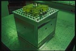
Figure 1: The LORS stage.
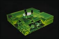
Figure 2: Zerodur metrology frame, with STM head.
Development of the stage continues. Current efforts at UNC-Charlotte to remove observed coherent Angstrom-scale oscillations should bring the stage's performance to its full potential. Concurrently, we have begun the design of a metrology atomic force microscope (AFM) head with the inherent accuracy of the system.
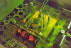
Figure 3: Inside the SAMM.
Description
AFM's have assumed a prominent role in the characterization of sample topographies on the atomic scale. As with other forms of scanned probe microscopy (SPM), AFM's provide orders-of-magnitude improvements in resolution over diffraction-limited optical methods. In practice, the AFM gains advantage over a number of other popular SPM techniques with its greater flexibility. Scanning tunneling microscopes, for instance, can only image samples with conductive surfaces, a restriction not applicable to AFM's.
Our design incorporates closed-loop control of a piezoelectric tube scanner, which guides a z-position sensor over the surface of the sample. We will use a miniature piezoelectric quartz tuning fork as the sensing element. As shown in various experimental studies, such a tuning fork may be used to detect atomic-scale surface features. In operation, we electrically excite the fork at its resonant frequency (2^15 Hz). When brought within roughly 10nm of the sample, near-surface atomic forces mechanically damp the fork's oscillations, altering the fork's electrical characteristics. While scanning in the X-Y plane, we will adjust the tube scanner's driving voltage to maintain a fixed fork impedance, thereby establishing a constant tip-sample separation. To create a topographic image of the sample, we simply record the relative extension or contraction of the scanner at each X-Y sampling point. To close the loop on the scanner, the head assembly will include a set of three capacitive gauges.
-
Project – Rotary Fast-Tool Servo for Diamond Turning of Asymmetric Optics
PI(S):
Sponsor(s):
Read more: Project – Rotary Fast-Tool Servo for Diamond Turning of Asymmetric OpticsWe have built a prototype turning machine specialized for the production of plastic spectacle lenses. This machine features a novel rotary fast-tool servo, which can track trajectories at frequencies up to 500 Hz, and accelerations of 500 m/s^2. Thus the machine can turn 100 mm diameter toric lenses having surface asymmetries of up to 3 cm in depth. The control system consists of a conventional inner position loop, feedforward filtering, and repetitive control. This high-bandwidth, high-accuracy system allows us to turn a toric surface with tracking errors of less than 2 microns.
Rotary Fast-Tool Servo for Diamond Turning of Asymmetric Optics
Acknowledgments
This project is funded by National Science Foundation under Grant award number DMI-9908325.
Description
Single-point diamond turning machines, such as lathes, are used to produce optically-clear parts. Conventional lathes carry the workpiece on a high-speed spindle and the tool on a slow axis allowing only rotationally symmetric shapes, such as spheres or paraboloids, to be machined. Asymmetric optics cannot be made using a conventional lathe, and are usually produced in a multi-step process of grinding and polishing. The diamond turning of asymmetric optics requires a fast-tool servo, which tracks a trajectory of higher frequency than the spindle RPM.
Figure 1 depicts the rotationally asymmetric surface of a eyeglass lens for the correction of astigmatism. This toric surface exhibits two peaks and two valleys per rotation of the lens. This means that if the spindle is turning at 1200 RPM, or 20 Hz, the tool servo must be able to follow a trajectory with a fundamental frequency of 40 Hz. Moreover, the servo must also track several higher harmonics (80 Hz, 120 Hz, 160 Hz, etc.,) to achieve the required accuracy.
Figure 1: Example of toric surface requiring a fast tool servo.
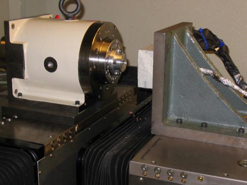
We have built a prototype turning machine specialized for the production of toric lenses, shown schematically in Figure 2, and photographically in Figure 3. This machine features a novel rotary fast-tool servo, which can track trajectories at frequencies up to 500 Hz, and accelerations of 500 m/s^2. The rotary topology eliminates the reaction force problems associated with linear fast-tool servos. Another advantage of the rotary structure is that it allows two arms to be mounted on a single axis, 180 degrees apart from each other on the shaft. Thus one arm can carry a robust and inexpensive polycrystaline tool for rough cuts, and the other can carry a delicate and expensive single crystal tool for finishing passes.
Figure 2: Schematic cross-section of rotary fast-tool diamond turning machine.
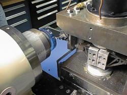
Figure 3: Photograph of rotary fast-tool diamond turning machine.
This machine can turn 100 mm diameter toric lenses with surface asymmetries up to 3 cm in depth. The control system consists of a conventional inner position loop, feedforward filtering, and repetitive control. This high-bandwidth, high-accuracy system allows us to turn a toric surface with tracking errors of less than 2 microns.
Current work is focused on reducing the manufacturing cycle time, improving the servo accuracy by an order of magnitude, and turning asymetric shapes in non-optic materials.
Publications
Stephen J. Ludwick, David A. Chargin, Joseph A. Calzaretta, and David L. Trumper, "Calibration and Control of a Rotary Fast-tool Servo," Proceedings of ASPE Fourteenth Annual Conference, October 1999.
-
Project – High-Accuracy Atomic Force Microscope for Dimensional Metrology
PI(S):
Read more: Project – High-Accuracy Atomic Force Microscope for Dimensional MetrologySponsor(s):
-
Project – Self-Bearing Motor Design and Control
PI(S):
Sponsor(s):
Read more: Project – Self-Bearing Motor Design and ControlThis thesis presents the design, implementation and control of a new class of self-bearing motors. The primary thesis contributions include the design and experimental demonstration of hysteresis self-bearing motors, novel segmented stator structures, MIMO loop shaping control algorithm for levitation and commutation, hysteresis motor analysis including frequency dependency, nonlinear hysteresis model including loop widening, and a novel single-axis self-bearing motor, as well as a zero power configuration for this type of motor.
Self-Bearing Motor Design and Control
In the late 1980s, the basic concepts of self-bearing motors were proposed. Since then, different types of AC and DC electric machines have been studied as a self-bearing motor. The self-bearing system is a key technology for high efficiency and compact systems with integrated magnetic levitation for high speed and high precision applications. One of the major disadvantages of existing self-bearing motors for high speed application is their rotor mechanical construction. Either the permanent magnet or induction machines rotor has mechanical features that introduces stress concentrations. Permanent magnets have very low mechanical strength and need to be inserted into the rotor. The assembly of magnets makes rotor vulnerable to mechanical failure at high speed. On the other hand, induction motors use soft steel to reduce hysteresis loss. Their rotors are slotted to either carry wires or in case of squirrel cages, having aluminum or copper bars.
As a promising alternative, this thesis demonstrates hysteresis self-bearing motors which have a simple construction with a solid and smooth rotor. This is a very important characteristic for some applications. This type of system can also be used as a magnetic bearing that can apply a finite amount of torque. The rotor doesn't have to be laminated and can be made from high strength steel. We designed, built and tested this type of self-bearing motor successfully.
In this thesis we also introduced a new type of segmented stator for hysteresis machines. The major advantages of this stator are: easy and low cost manufacturing, higher filling factor and higher motor efficiency. We tested the self-bearing concept successfully with this new configuration.
We have also introduced a novel single axis self-bearing motor that is very suitable for rotors with large length to diameter aspect ratio, such as high speed flywheels for energy storage. We implemented a zero power levitation condition along with passive damping for this system that has several advantages for high speed systems. One of the major advantages of zero power systems is the simple and robust touch down bearing design which is a key element for active magnetic bearings and self-bearing motors. This is mainly because the bearings experience minimal load in case of power failure.
Hysteresis is a time-rate dependent phenomena which is fundamentally related to eddy current formation in the material and the thermal agitation. Hysteresis loops of materials with large hysteresis are highly frequency dependent. Therefore we added hysteresis frequency dependency to hysteresis motor analysis, which is believed to be a novel contribution. We have also developed linear and nonlinear analyses for the stabilizing forces and moments for hysteresis self-bearing motor. The nonlinear analysis is based on Chua's nonlinear hysteresis model that includes loop widening. The theoretical results were verified by experimental data for three different type motor configurations with good accuracy.
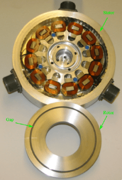
Figure: Segmented stator design
-
Project – Design and Testing of a High Accuracy Robotic Single-cell Manipulator
PI(S):
Sponsor(s):
Read more: Project – Design and Testing of a High Accuracy Robotic Single-cell ManipulatorWe have designed, built and tested a high accuracy robotic single-cell manipulator, which is able to pick individual cells from array of microwells, each 30 μm or 50 μm cubed. Design efforts have been made for higher accuracy, higher throughput, and compactness. The proposed system is designed to have a T-drive mechanism with two linear stages for XY-plane positioning to have higher stiffness and less structurally inherent error. Precision is especially required in Z-axis movement for successful cell retrieval procedure and so a rotational mechanism with a voice coil actuator, among many options, is selected for the Z-axis motion because this results in relatively smaller reaction on the system and has advantages of direct drive. The prototype of the robotic single-cell picker integrates the Z-axis and XY stage motion, real-time microscopy imaging, and cell manipulation with a NI PXI-controller centered as a main real-time controller. This prototype is built to test performances of the proposed system in terms of single-cell retrieval. We conducted experiment for the cell-retrieval process with microbeads of the equivalent size to mammalian cells, and it has shown promising results.
This proposed system will be used to help select and isolate an individual hybridoma from polyclonal mixture of cells producing various types of antibodies. It is important to be able to do this cell-retrieval task since a single isolated hybridoma cell produces monoclonal antibody that only recognizes specific antigens, and this monoclonal antibody can be used to develop cures and treatments for many diseases. Our research's development of accurate and dedicated mechatronics solution will contribute to more rapid and reliable investigation of cell properties. Such analysis techniques will act as catalyst for quicker discovery of treatments and vaccines on a wide range of diseases including HIV infection, tuberculosis, hepatitis C, and malaria with potential impact on the society.
Design and Testing of a High Accuracy Robotic Single-cell Manipulator
Introduction
We have designed, built and tested a high accuracy robotic single-cell manipulator to be able to pick individual cells from array of microwells, 50 μm each. Design efforts have been made for higher accuracy, higher throughput, and compactness. This proposed system will be used to help select and isolate an individual hybridoma from polyclonal mixture of cells producing various types of antibodies. It is important to be able to do this cell-retrieval task since a single isolated hybridoma cell produces monoclonal antibody that only recognizes specific antigens, and this monoclonal antibody can be used to develop cures and treatments for many diseases.
Design of Single-Cell Manipulator
The proposed system is designed to have a T-bar mechanism with two linear stages for XY plane positioning to have higher stiffness and less structurally-inherent error. Figure 1 shows the schematic design of the proposed system, robotic single-cell manipulator.
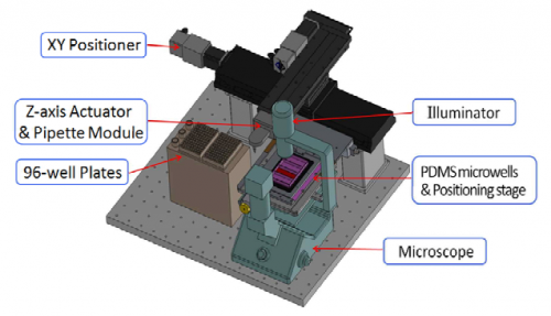
Figure 1
Precision is especially required in Z-axis movement for successful cell-retrieval procedure. Having independent structure for the Z-axis motion on the XY positioning mechanism which provides large stiffness, the proposed cell-picker is designed to minimize error. Among many options considered for Z-axis motion, a rotational mechanism with a voice coil actuator is selected because this results in relatively smaller reaction on the system and has advantages of direct drive.
Prototype of the Proposed System
An old hard disk drive system is utilized to obtain Z-axis motion since it has a well-constructed electromagnetic motor and also well-built-in bearing. Arm extension, shown in Figure 2, has also been designed, constructed, and assembled to meet the design requirements of the system. Since the voice coil motor has a relatively small torque constant of 0.4 Nm/A, it is important to counter-balance the arm.
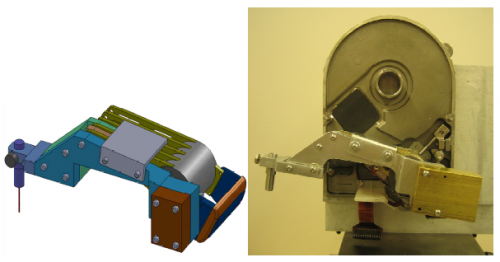
Figure 2
The prototype, illustrated below in Figure 3, integrates the Z-axis and XY stage motion, real-time microscopy imaging, and cell manipulation with a NI PXI-controller centered as a main real-time controller.
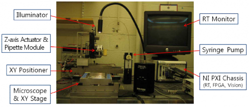
Figure 3
An inverse microscope is also self-designed and constructed assembling a charge-coupled device (CCD) camera and a zoom lens specified enough to observe a 10 μm cell or microbead, and a microscope stage with the resolution of submicron. In addition, a syringe pump, together with a glass pipette, is used to aspirate and dispose individual cells out of Polydimethylsiloxane (PDMS) microwells and into 96 well plates with the control of appropriate liquid amount and speed.
Results and Conclusions
This prototype is built to test performances of the proposed system in terms of single-cell retrieval. This cell-retrieval is experimentally tested with the equivalent size, 10 μm, of microbeads. Figure 4 below shows one block of PDMS microwells containing a number of 10 μm microbeads; the left figure is before the cell-retrieval and the right one is after.
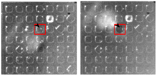
Figure 4
The small white dot pointed with a block arrow indicates the picked microbead. The retrieval process itself takes average of 5 to 10 seconds depending on how long microbeads have stayed in microwells. The testing of the prototype results in reliable cell-retrieval with the success rate of more than 90 percent. More experiments with actual living mammalian cells will be conducted as a future work.
-
Project – Design and Control Methods for High-Accuracy Variable Reluctance Actuators
PI(S):
Read more: Project – Design and Control Methods for High-Accuracy Variable Reluctance ActuatorsSponsor(s):
-
Project – Portable Control Systems Laboratories
PI(S):
Read more: Project – Portable Control Systems LaboratoriesSponsor(s):
-
Project – Modeling and Compensation of Spatial Disturbances on Reluctance Actuators
PI(S):
Read more: Project – Modeling and Compensation of Spatial Disturbances on Reluctance ActuatorsSponsor(s):
-
Project – Magnetically Suspended Reaction Sphere
PI(S):
Read more: Project – Magnetically Suspended Reaction SphereSponsor(s):
-
Project – Non-Operative Correction for Long-Gap Esophageal Atresia
PI(S):
Read more: Project – Non-Operative Correction for Long-Gap Esophageal AtresiaSponsor(s):
-
Project – Ultra-High Performance Fast Tool Servos for Diamond Turning
PI(S):
Sponsor(s):
Read more: Project – Ultra-High Performance Fast Tool Servos for Diamond TurningWe have designed, implemented, and tested an electromagnetically driven fast tool servo for diamond turning precision contoured surfaces with nanometer resolution. Our device is based on a novel ultrafast motor utilizing permanent magnets for flux bias in conjunction with steering coils used to control the actuator force. Experimental results demonstrate that our ultrafast tool servo has a stroke of 30 micrometers, achieves 23kHz closed-loop bandwidth, as low as 1.7nm RMS tracking error, 500G peak acceleration at 10kHz open-loop operation, and 2.1nm (0.04%) error in tracking a 3kHz sinusoid of 16mm p-v. To drive and control this ultrafast tool servo, a 1kW linear power amplifier and a high-speed real-time computer with 1MHz sampling rate have been designed and implemented.
Acknowledgments
This project is funded by National Science Foundation under Grant award number DMI-0322590.
Motivation
Manufacturing free-form optical surfaces increasingly requires fast tool servos with higher bandwidth, higher acceleration, and higher accuracy. As an alternative solution to conventional piezo-based micro-positioning devices, electromagnetic actuators working on normal stress can potentially achieve much better performance than existing state of fast tool servo technology.
Objectives
Design ultra-high performance fast tool servos based on novel electromagnetic actuators, high performance precision power amplifiers, and high performance real-time computers.
Results
Our fast tool servos performance: 23kHz closed-loop bandwidth, 1.7 nm RMS positioning error, 2.1 nm RMS error for tracking 16 micron peak-to-valley sinewave at 3k Hz, 500 G acceleration up to 10 kHz.
Our linear amplifier has 100kHz band and 1 kW.
Our real-time computer has achieved 1 MHz sampling rate for a control loop including 16-bit A/D, control algorithm calculation, and 16-bit D/A.
Publications
Xiaodong Lu, David L. Trumper, "UltraFast Tool Servos for Nano-Surfaces", Proceedings of ASPE 2004 Annual Meeting, Orlando, FL.
Xiaodong Lu, David L. Trumper, "Ultrafast Tool Servos for Diamond Turning", Annals of the CIRP 2005, accepted for publication.

-
Project – FlexLab and LevLab
PI(S):
Read more: Project – FlexLab and LevLabSponsor(s):
-
Project – Magnetically Levitated BLDC Motor
PI(S):
Read more: Project – Magnetically Levitated BLDC MotorSponsor(s):